This guide will show you the steps necessary to turn a commercially available Xiaomi MADV (mijia) into a fully functioning, animal sensitive, weatherproof Camera trap!

Code
Code is available in this repo https://github.com/Digital-Naturalism-Laboratories/Panatrap/tree/master/MADV
Hardware
Physical Designs are available here for free download: https://a360.co/2nrPLd8
and included in the Github https://github.com/Digital-Naturalism-Laboratories/Panatrap/tree/master/MADV
Hacking Theory
The MADV designers made an interface on the bottom of the camera for the camera to be easily controlled with their included “selfie stick.” It’s just two metal electrode contacts that when connected it sends a message to the camera(the original selfie stick has a 220 ohm resistor connected to a button).
From our examinations, the 3 messages you can send to the camera with this interface are:
- Long Press (5 seconds)
- Camera ON/OFF
- Medium Press (2 seconds)
- Toggle Recording Mode (Video to Photo, or Photo to Video)
- Short press (0.5-1 seconds)
- Shutter Button (Take a photo, or start or stop a video)
Cut out or Print the Design
You will need to cut out two main parts of the design:
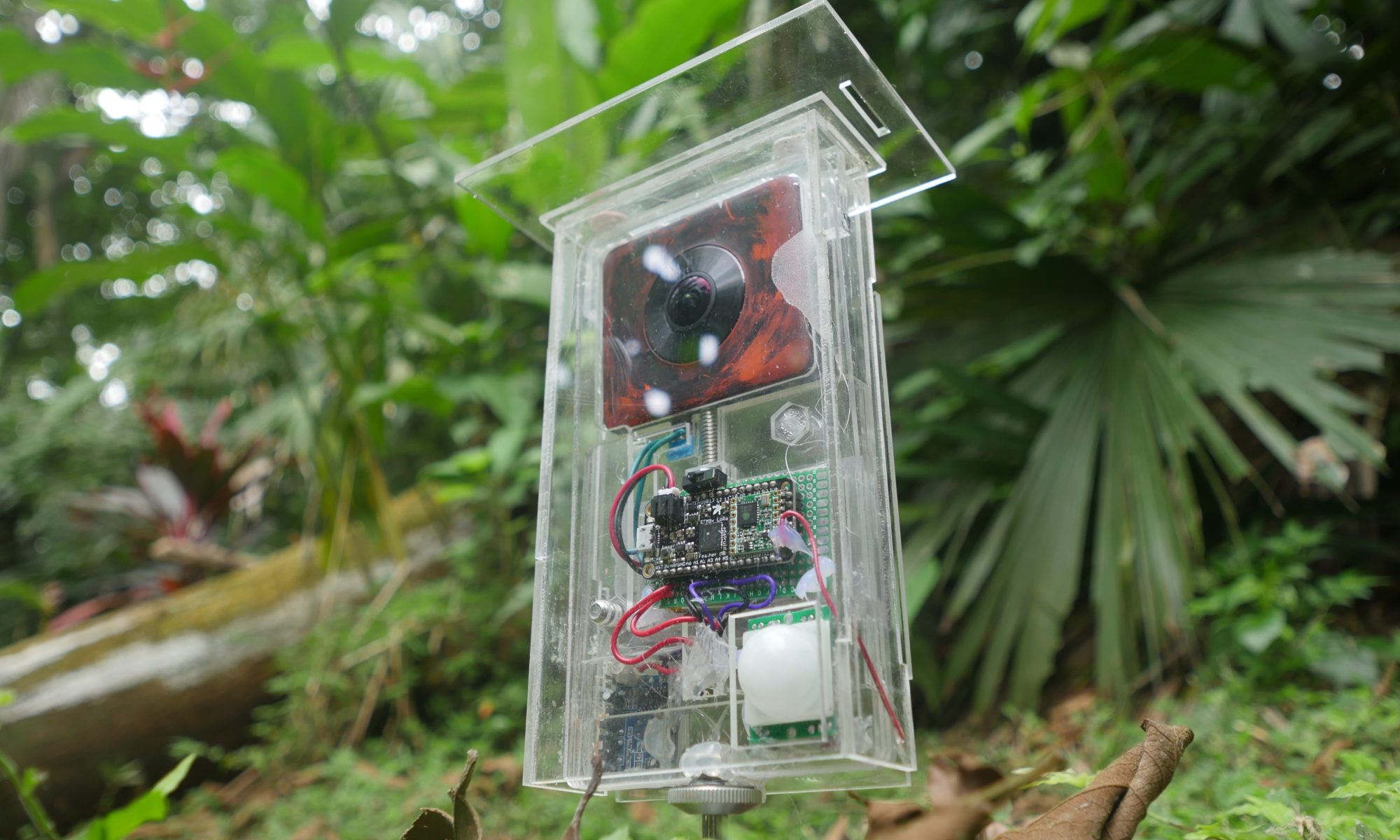
The Housing – These are the parts that will go around the camera and Arduino, and hold all the pieces together to make the project function
The Weather Shield – This is a 360-degree transparent case that lets the camera stand up again
In the link and the repo, these are 2-dimensional drawing files mean to be laser cut from 3mm acrylic. The full 3D model is there, though, so you could 3D print the housing instead if you don’t have a laser cutter.
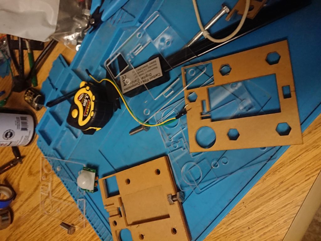
I kept the the weather shield quite simple in design as well, so if you do not have a laser cutter, you can pretty much just make a box from clear acrylic that goes aroundDIY
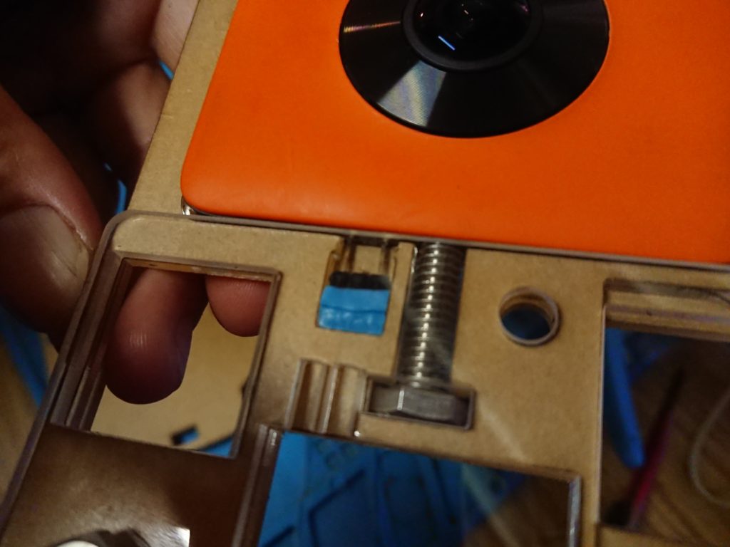
DIY Pogo Pins / Prepare the Contact Connector
Ideally you would have these things called “Pogo pins” which are little spring mounted pins that press against electrical contacts such as those on the bottom of your MADV. If you have those, great! solder wires to two of them with one header pin space in between.
If you are out in the jungle, and don’t have Pogo pins, though, we can make our own ones. You just need:
- Standard Male Header pins (3 linked together)
- Chunk of hard rubber (we used a piece of our silicone soldering mat)
- 2 wires
Take your set up 3 header pins, chop off the middle pin, and stab them all into the hunk of rubber cut to the size of the area in the camera housing for the electrodes. Solder two wires to the outside pins. They should line up directly with the electrical contacts of the camera. The rubber gives the mechanism some squishiness, so you can ensure a good contact with the camera.
Connect all the Electronics
Now you just need to connect the components together!
The camera has two electrical contacts you just put together. The wire running to the contact closest to the center of the camera should go to the GND pin on your arduino.
The outside wire contact should go to pin 12 on your arduino.
Now you just need to connect the PIR motion sensors.
PIR
If you are using a 5V power source,
simply connect the Vin lines on the PIRs to the 5V on the arduino
The GND to the GND on the Arduino
and the OUT pins on the PIR to pins A4 and A3 on your arduino
Program
The code is all up at: https://github.com/Digital-Naturalism-Laboratories/Panatrap/blob/master/MADV/Code
This first, simple sketch should let you debug easily and make sure your PIR’s are working and your camera is triggering and shutting down correctly
/*
PanaTrap - MADV
Debug Code for the turning the Xiaomi MiSphere (MADV) camera
into a remotely controlled,
PIR triggered, Camera Trap
*/
/* in order to trigger the MADV camera to change modes, in theory you should connect a relay to your arduino, and trigger that to connect the nodes of the MADV
//But we are trying to use minimal hardware, and found that if you connect the node closest to the center of the camera to the ground, and then
//Connect another digital pin to the other node
//Initially set the digital pin to HIGH, and then when you pull it LOW
//it will trigger the camera
- Long Press (5 seconds)
- Camera ON/OFF
- Medium Press (2 seconds)
- Toggle Recording Mode (Video to Photo, or Photo to Video)
- Short press (0.5-1 seconds)
- Shutter Button (Take a photo, or start or stop a video)
*/
//Front PIR motion sensors
int fPIR = A4;
int fPIRval = -1;
//Back PIR motion sensors
int bPIR = A3;
int bPIRval = -1;
//camera trigger operants
int trigger = 12;
int gndtrigger = 9;
//LED for debugging display
int led = 13;
void setup() {
//Serial for debugging PIRs
// initialize serial communication at 9600 bits per second:
Serial.begin(9600);
//Turning some of the pins on the camera into virtual Power sources and Grounds
pinMode(A1, OUTPUT);
digitalWrite(A1, LOW);
pinMode(A2, OUTPUT);
digitalWrite(A2, HIGH);
pinMode(A5, OUTPUT);
digitalWrite(A5, LOW);
//Camera Trigger stuff
pinMode(led, OUTPUT);
pinMode(trigger, OUTPUT);
pinMode(gndtrigger, OUTPUT);
digitalWrite(led, HIGH);
digitalWrite(trigger, HIGH);
digitalWrite(gndtrigger, LOW); //**Andy note A
}
// the loop routine runs over and over again forever:
void loop() {
// read the input on analog pin 0:
fPIRval = analogRead(fPIR);
bPIRval = analogRead(bPIR);
// print out the value you read:
Serial.print(fPIRval);
Serial.print(" rear: ");
Serial.println(bPIRval);
if (fPIRval > 600 || bPIRval > 600) {
critterDetected();
}
delay(1); // delay in between reads for stability
}
void critterDetected() {
Serial.println("Critter detected");
//Turn camera on
onOffCamera();
//Take a photo
takePhoto();
takePhoto();
//TODO: Wait to see if other critters still around
//before we shut off camera
//TODO: the camera will toggle between photo and video each time it shuts off, add in a toggle here
onOffCamera();
}
void onOffCamera() {
Serial.println("cameraONOFF");
//5 second turn on
digitalWrite(led, LOW);
digitalWrite(trigger, LOW);
digitalWrite(gndtrigger, LOW);
delay(5000);
///Chill
digitalWrite(led, HIGH);
digitalWrite(trigger, HIGH);
digitalWrite(gndtrigger, LOW);
delay(2000);
}
void takePhoto() {
Serial.println("Take photo");
//Take a photo
digitalWrite(led, LOW); // turn the LED off by making the voltage LOW
digitalWrite(trigger, LOW); // turn the LED on (HIGH is the voltage level)
digitalWrite(gndtrigger, LOW);
delay(1000); // wait for a second
///Chill 4 secs
digitalWrite(led, HIGH);
digitalWrite(trigger, HIGH);
digitalWrite(gndtrigger, LOW);
delay(4000);
}
void togglePhotoVideo() {
Serial.println("cameraTogglePhotoVideo");
//2 second press
digitalWrite(led, LOW);
digitalWrite(trigger, LOW);
digitalWrite(gndtrigger, LOW);
delay(2000);
///Chill
digitalWrite(led, HIGH);
digitalWrite(trigger, HIGH);
digitalWrite(gndtrigger, LOW);
delay(2000);
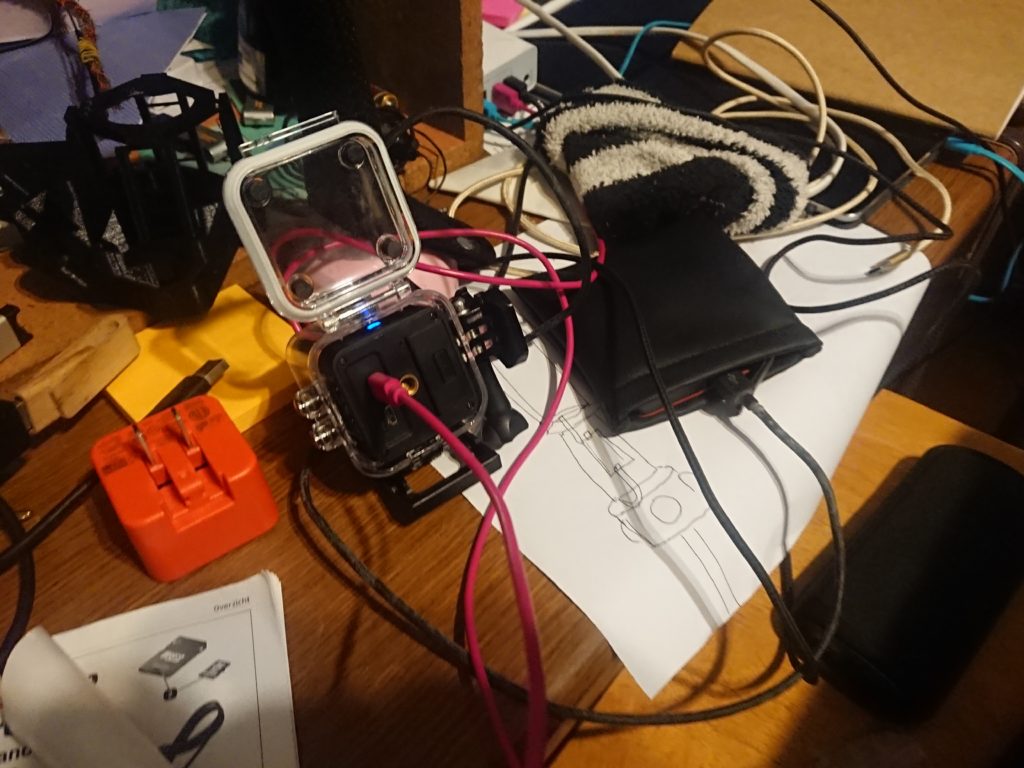
}Charge all your devices
In this build, the MADV has its own internal battery, and the Arduino is connected to its own re-chargeable LIPO
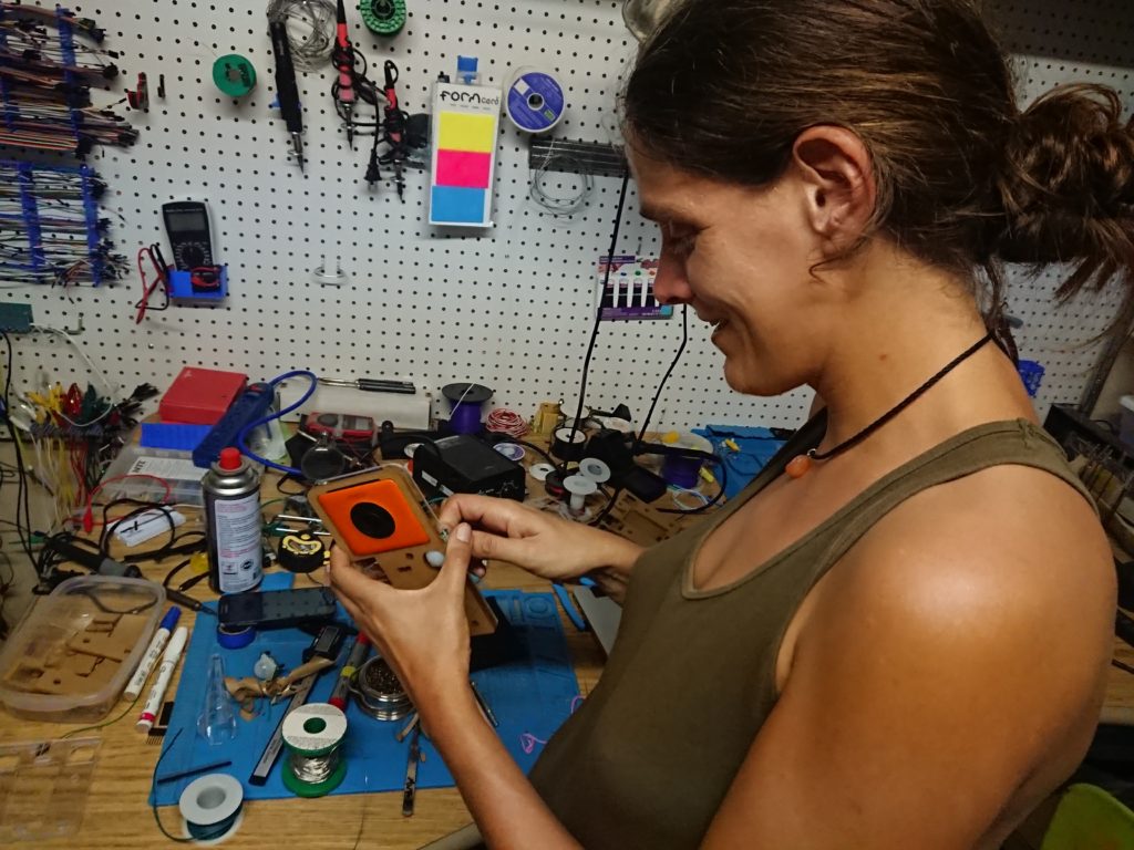
Assemble and Deploy
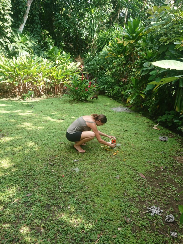
Now that it is ready, give the PIR’s a quick wave, and test that everything is triggering. Now set it in the target environment, and test it again by jumping in front of it and seeing if you can detect it. (You will have lots of 360 selfies with testing this camera).
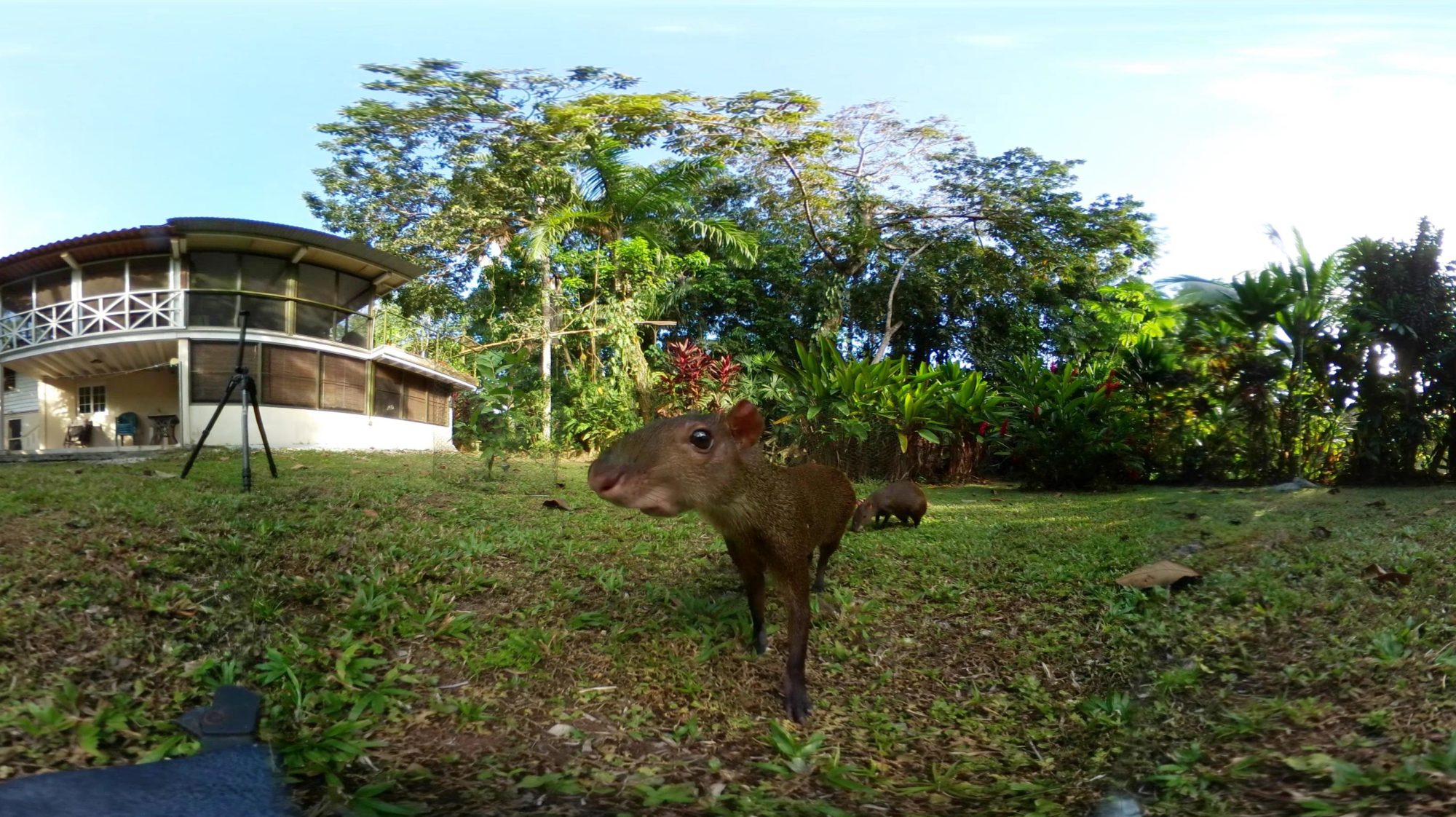
If it all seems good, leave it there and come check on it in a couple hours or days and see what you caught!